

M2A2448-23GC
M2A-G series is a new series of products upgraded on the basis of the structure of the first-generation MIA-G product series of ZDS, which further enhances the compatibility of the products. M2A-G series cameras are developed based on GigE Vision and are compatible with third-party machine vision development software. It is especially suitable for applications that have strict requirements on stability, compatibility, volume and cost performance.
| Parameter | Value |
|---|---|
| Resolution | 2448x2048 |
| BIN | - |
| SUM | - |
| Minimum ROI | 32 x 32 , Minimum step 8 |
| Other Resolution | 1920x1080 1080P 103FPS - 1224x1024 SKIP 198FPS |
| Optical Sensor | 2/3" |
| Shutter Technology | Global |
| Pixel Size | 3.45um |
| Max Frame Rate | 23FPS |
| Mono/Color | Color |
| Resolution | 2448x2048 |
| Sensor Size | 8.45mm x 7.07mm |
| SNR | 36.6 db |
| Sensibility | 1.146V/Lux.S 1/30S F5.6 |
| Bit Depth | 12bit |
| Trigger | Software/Hardware Trigger |
| Dynamic Range | 72db |
| Spectral | 390nm-650nm |
| Image Format | BGR24, RAW8, RAW16, MONO8, MONO16 |
| Photo Support Format | RAW BMP JPEG PNG |
| Power Supply | POE or 12V DC |
| Power Consumption | ~2.3W |
| Interface | GigE |
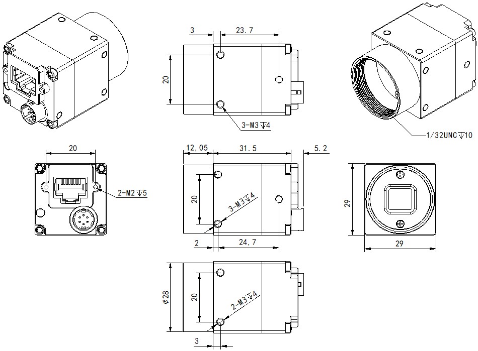
| Dimention | 29mm×29mm×31.5mm |
| Work Temperature | -10℃ - 50℃ |
| Weight | 40g |
| Lens Mount | C |
| IP Protection | IP30 |
| Compatibility | GigEVision, GenlCam, HALCON, LabView, OpenCV |
| Certification | CE, FCC, RoHS |
Key Features
- Second-generation industrial camera, low power consumption
- A new generation of appearance structure design, higher Installation accuracy
- noise reduction, super palette, User-defined key and other rich functions.
- GigE interface, maximum transmission distance up to 100m (without relay)
- Support GigE Vision V1.2, GeniCam standard, seamlessly connect to third-party software
- Comply with CE, FCC, RoHS
- Dimension: 29 mm × 29 mm × 31.5 mm
Dimension(Unit: mm)
Interface Definition
| Pin | Color | Definition | Signal Source | Description | Isolated/non-isolated | Interface Circuit | Input/Output Parameters |
|---|---|---|---|---|---|---|---|
| 1 | Red | POWER_IN | DC Power Supply Positive | DC 12V~24V(±10%) | |||
| 2 | Green | TRIG+ | Line 1+ | Trigger input positive | Isolated | optocoupler | Low effective: 0-1V _ High effective: 5-24V |
| 3 | White | GPIO | Line 3+ | General Purpose Inputs and Outputs | non-isolated | Input low effective: 0-0.7V _Input high valid: 2.9-3.6V_Output low level: 0V_Output high level: 3.6V | |
| 4 | Yellow | Flash_out+ | Line 2+ | Flash output positive | Optocoupler current limit: 20mA | ||
| 5 | Brown | COM | Line 1/2- | Trigger/flash optocoupler common (negative) | |||
| 6 | Black | GND | Line 3- | Power negative/GPIO ground | |||
| Transparent | shielding cable | Connect to camera housing | Remarks: Transparent heat-shrinkable tubing for shielded wire cover | ||||
| Pin | Color | Definition | Signal Source | Description | Isolated/non-isolated | Interface Circuit | Input/Output Parameters |